Trial Period or Updates Expiring? Email Trial ID to Support
Thank you for testing MillMage!
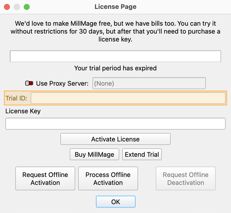
Release Candidate users who see a "Your trial period has expired" notice when opening MillMage can request an extension to the update period by emailing the MillMage Trial ID to the Support team.
Find your Trial ID in the License Management window. Email your Trial ID to [email protected] to start your request. The duration of the extended update period may vary.
Warning
The current version of MillMage is a Release Candidate — a stable version of software that is nearly ready for official release, but in need of additional public testing. Please report any unexpected behavior in the MillMage Software Questions section of our forum, including screenshots and as much detail as possible. Ask hardware compatibility questions in the MillMage Hardware Compatibility section.
Users new to MillMage should follow the Getting Started guide.
Video: How to Use a Release Candidate
This video features our sister software, LightBurn. While there may be slight differences in appearance and layout, the demonstrated processes are similar in MillMage.
Warning
This documentation is in active development and in a prerelease state. These documents are not complete and may include missing pages, broken links, and placeholders. Content is being updated as feedback is reviewed. Your patience is appreciated.
MillMage Project: Hello World
Create your very first CNC cuts in MillMage using any piece of compatible material. This step-by-step tutorial will walk you through making your first cuts with a CNC machine.
In this project, you will learn about:
- Creating a design with the Draw Shapes tool
- Adding and editing Text
- Scaling and Aligning objects to each other
- Adding tooling to the Tool Library
- Assigning Pocket and Profile CNC Operations to shapes
- Adding machined object retention Tabs to Profile operations that cut through the material stock
- Previewing the results of the assigned operations, speeds, and feeds
- Starting CNC Jobs
- Removing objects retained with Tabs

Every CNC Machine is Different
CNC cutting and engraving performance, quality, and speed is highly machine & user-dependent. Beginners are advised to familiarize themselves with their CNC manufacturer user guide and manual prior to using a CNC machine with MillMage.
Recommended Materials
Choose a material to get started, larger than 150 mm (6 inches) if using ¼ inch tooling like:
- Softwoods like pine and bamboo
- Soft & hardwood plywood (Grade A or B)
- Manufactured materials like MDF — Medium Density Fiberboard
Material Selection Tips
Choose unwarped materials that lay flat and can easily fit within the work area of your CNC machine.
Materials to Avoid
- OSB — Oriented Strand Board — plywood
- Particle board
- Hardboard or HDF High Density Fiberboard
Tools Required
- CNC Machine
- Machine-specific workholding equipment such as T-track clamps, screws & drivers, and/or adhesives
- Router Tooling
- ⅛ inch or ¼ inch end mill, or any other available tooling with a small cutting diameter
- A flat piece of paper for zeroing out the Z Axis
- Digital or analog vernier calipers for measuring tooling and material stock
- Measuring tape if using a large workpiece
Personal Protection Equipment (PPE) Required
Personal Protection Equipment (PPE) & Safety Precautions
Recommendations:
- Eye Protection, in the form of safety glasses or goggles rated for impact resistance, to prevent vision loss.
- Hearing Protection, with a measured Noise Reduction Rating (NRR) in the form of foam in-ear plugs or ear muffs, to prevent hearing loss.
- Protective Footwear, non-slip, thick-soled, and fully enclosed, to prevent falls and accidental puncture injuries from tooling and cutting debris.
- Glove-free Hands, to prevent getting caught in moving machinery.
- Secured Hair, pulled back away from the face, to prevent getting caught in moving machinery.
- Close-fitting Clothing without drawstrings, to prevent getting caught in moving machinery.
- Jewelry-free Hands, Wrists, and Neck, to prevent getting caught in moving machinery.
Your First CNC Operations with MillMage
Create Design
-
Open MillMage and select the desired CNC machine from the Machine drop down in the Project Setup Window.
- Measure your material stock and update the dimensions in Stock Dimensions
- Update the remaining values in the Project Setup Window to match your current setup, or accept the default values and click OK to close the Project Setup Window.
We will update these values later in this guide to match your CNC machine setup. View more details at: Project Setup Window.

Remember
Need to change your material stock dimensions?
Edit your project in the Project Setup Edit window by clicking CNC Tools → Project Setup Edit
-
The MillMage Workspace will now display the available cutting area for your design within the dimensions of the material stock as defined in the Project Setup Window.
Activate the Draw Shapes tool — found in the Creation Tools toolbar on the left-hand side of the window by default. The active tool icon within the toolbar color will change from black to red when active.
-
Draw a rectangle or circle large enough to accommodate the tooling kerf and the text content we will be adding later. Create the shape by clicking & holding the mouse button while dragging the shape edges across the available design area, leaving space around the edge of the Workspace — the visual representation of the machinable material stock. Users with ¼ inch tooling should create the shape at least 150 millimeters (~6 inches) in width or height within the MillMage workspace to accommodate all of the text content.
Optionally, precisely adjust the dimensions of this shape as desired by editing the displayed values in the Width and Height portion of the Numeric Edits toolbar. Click on the
 padlock icon to unlock the aspect ratio. Click on mm or in to switch between units.
The Preview — introduced later in this guide — window can be used to verify that all the objects can be created with the selected tooling. MillMage will only cut design elements that can fit in the assigned tooling.
-
Add text to the area within the shape by clicking on the Text tool found in the middle of the Creation toolbar and clicking on your desired text location. Type "Hello World" or your desired text and adjust as desired.
-
Click on the
 Select tool or press the esc key twice to cancel any active selections and to switch to the text tool. Select the text. Selected artwork will be indicated with an animated dashed line.
 -
Adjust the scale of the text as desired by clicking and dragging on one of the four gray boxes in the corner until the text fits comfortably within the shape. Ensure that either the height or width of the text is wider than 150 mm (5.9 in). If the text elements are too small, larger router bits may not be able to cut within that area and may not be output by MillMage. Roughly adjust the positioning of the text by clicking and dragging on the small gray center handle in the center of the artwork.

-
Center the text artwork within the enclosing rectangle with the Align V-Center and Align V-Center tools.
A. Select both elements by clicking within the workspace and dragging —the bounding selection box will be drawn in red when drag-selecting to the right, indicating that all elements need to be fully enclosed to be selected, and alternatively drawn in green when drag-selecting to the left to indicate selection of elements that fully and partially touch the bounding selection box.
B. Press the
 Vertical Align icon → Align V-Center tool to align the artwork along the vertical centerline of the last selected asset.
C. Press the
 Horizontal Align icon → Align H-Center tool to align the artwork along the horizontal centerline of the last selected asset.
 -
Save the project by selecting the
 Save icon in the main toolbar or by pressing ctrl + s, naming this project and the file save location as desired.
Assign Operations
Assign cut operations to each artwork element through the Operation Editor found by default on the far right-hand side of the MillMage interface. The order of operations matters — MillMage will process each operation sequentially from top to bottom when more than one operation is selected.

Best Practices: Operations Ordering
Order operations like Profile cuts that cut objects free from the material stock last, to help prevent parts from shifting or flying free during other operations. Run all non-cut through operations first.
-
Click the New Operation → Pocket button to begin assigning operations — a Pocket operation first to remove all material within the text elements.

-
Press the Select Tool button and choose a beginner-friendly tool like an ⅛" or ¼" flat end mill. A tooling preview will be displayed in the right-hand side of the Select Tool from Library window. Review & verify the tooling specifications in the Tool Properties. Refer to the router bit manufacturer for specific tooling details. Learn how to add tooling in the Add Tooling guide.
Remember
More complex tooling such as ball end mills and V-bits should be reserved for future beginner-friendly projects.

-
Press Select Tool or double-click on the desired tool to assign the highlighted tool to the operation and automatically close the tool selection window. Project specific Speeds and Feeds will be updated within the Operation Settings Editor window later in this guide.


-
Set the Clearing Pattern dropdown to Offset, to make the router bit trace concentrically within the line paths of the text designs. Leave the Cut Direction set to Conventional — where the tooling pushes down on the material being cut.

Pocket Clearing Patterns
Offset-
Router bit traces concentrically within the line paths of the design elements
Raster-
The router bit will move back and forth across the X axis to clear out the material within the line paths of the design elements.
-
Set and review the cutting parameters in the Depths and Entry section, deferring to tooling manufacturer specifications:
- Start Depth: 0.00 mm as this project zeros out on the top surface of the workpiece
- Final Depth: at least: 1.5 mm (1/16 in)
- Depth Per Pass: generally ½ the diameter of the tool, in this example 1.5 mm (1/16 in)
- Step Over: the width of the router bit that will be engaging into the material stock during the clearing operation: 1.5 mm, deferring to tooling manufacturer specifications
- Entry Type: Plunge, which drives straight down into the material before traveling horizontally to cut
- Lift Height: overrides the Fast Retraction Height values set in initial Project Setup if set to a non-zero value: 0.00 mm
- Ramp Angle: Leave at 22.50

-
Review and set the tooling values in the Feeds and Speeds section according to the recommendations of the tooling manufacturer for the selected material stock.
Recommended Router Bit Speeds and Feeds

-
Select OK to close the Operations Editor.

-
Select the text with the Selection tool, select the Pocket operation, and click Assign Shapes to assign the Pocket operation to the text elements. The text will be displayed with a bold, animated dashed line when assigned to an operation.


-
Profile outside
-
Create tabs
-
Select tooling and assign speeds/feeds
-
Verify the upcoming CNC operations by making sure each listed operation output is toggled on in the Operations window.

-
Save the project by selecting the
Save icon in the main toolbar or by pressing ctrl + s.
Preview Job Operations
-
The Preview tool allows you to preview the movements and cutting path the CNC machine will take and will give an estimated time of how long the machining program will take.

-
Press the Preview button
 to open the Preview window.
-
The left-hand side of the Preview window will display a virtual representation of the upcoming cuts. The right-hand side displays the tooling travel (non-cutting) in red and the cutting paths in black. Clicking and dragging within each side will manipulate the view point. Scrolling with the mouse wheel will zoom in and out of the view.

-
Press Play to view a real-time simulation of the upcoming operations. Optionally adjust the Playback Speed to increase or decrease the simulation speed.

-
Click Ok when the simulation ends and when satisfied with the simulated operations.
View the troubleshooting preview images guide here: #

Potential Causes:
- Design elements not assigned to CNC operation
- Resolution: Assign missing elements to a CNC operation.
- Resolution: Click on the first operation listed and the Select Shapes button to highlight the design elements assigned to that operation. Add missing elements by shift selecting designs and pressing Assign Shapes to associate the design with that operation.
- CNC Operations Output setting is not active
- Resolution: Toggle Output from off to on.
- Design too small for tooling
- Resolution: Scale design larger by selecting the element and using the scale handles.
- Tooling too large for design
- Resolution: Switch to tooling with a smaller cutting diameter.

Potential Causes:
- Design too small for tooling
- Resolution: Scale design larger by selecting the element and using the scale handles.
- Tooling too large for design
- Resolution: Switch to tooling with a smaller cutting diameter.
- Multiple operations are assigned to single design elements
- Resolution: Reassign shapes to operations
- Profile operation applied to text elements
- Resolution: Assign Pocket operations to text elements.
- Resolution: Switch to single line SHX fonts.
- Profile operation set to follow design lines Along line, Inside the lines, or Outside of design line paths.
- Resolution: Switch Profile Line behavior to different selection.

Potential Causes:
- Sed sagittis eleifend rutrum.
- Donec vitae suscipit est.
- Nulla tempor lobortis orci.
Put On PPE
Personal Protection Equipment (PPE) & Safety Precautions
Recommendations:
- Eye Protection, in the form of safety glasses or goggles rated for impact resistance, to prevent vision loss.
- Hearing Protection, with a measured Noise Reduction Rating (NRR) in the form of foam in-ear plugs or ear muffs, to prevent hearing loss.
- Protective Footwear, non-slip, thick-soled, and fully enclosed, to prevent falls and accidental puncture injuries from tooling and cutting debris.
- Glove-free Hands, to prevent getting caught in moving machinery.
- Secured Hair, pulled back away from the face, to prevent getting caught in moving machinery.
- Close-fitting Clothing without drawstrings, to prevent getting caught in moving machinery.
- Jewelry-free Hands, Wrists, and Neck, to prevent getting caught in moving machinery.
Setup CNC
Every CNC Machine is Different
Always refer to CNC manufacturer instructions and guidelines for recommended machine setup proceedures. Failure to follow CNC manufacturer guidelines can lead to damaged property, bodily harm, or death.
-
Ensure CNC work area is clear of foreign objects and debris. The material stock should not be inside the CNC machine cutting area at this time.

-
Power on the CNC machine.
-
Physically connect the CNC machine to the computer running MillMage using a USB cord or over the network through an Ethernet cable. Rarely, some users may need to save GCode files to a flash drive to run locally on their CNC machine.
-
Open a connection to the device, by selecting the proper COM port in the CNC Control window. The CNC Control window will display "Connected" when communication with the CNC machine has been established.


-
Click on the Move tab to open the Move window. Home the CNC machine to establish machine zero (position 0.0 along the X, Y, and Z Axis) by pressing the
 Home button. Wait until the homing process completes.

-
Move tool head away from the origin as needed in the Move window for additional accessibility, lowering the move distance as needed as the tool head approaches each axis travel limit.
Workholding: Securing the Material Stock
Warning
Secure the material stock to the CNC machine by following the CNC manufacturer workholding guidelines.
FAILURE TO FOLLOW CNC MANUFACTURER WORKHOLDING RECOMMENDATIONS CAN LEAD TO DAMAGED PROPERTY, BODILY HARM, OR DEATH.
Verify that the material stock is properly secured by vigorously pushing and pulling against the workpiece in all directions.
View the Workholding Guide for examples.
Measure the Safe Clearance Height & Update Project Setup
-
Open the Project Setup window by selecting CNC Tools → Project Setup Edit.

-
Measure the height of any work holding devices using digital or analog vernier calipers and record this value. If clamps are not used, measure from the top surface of the CNC work area to the top of the material stock and update the Safe Clearance Height entry to a number slightly larger than the measured value. This value is used when the CNC machine tool head is lifted clear of these and other obstructions prior to moving along the X and Y axis.


-
Remeasure and verify or update the material thickness, from the surface of the CNC work area or waste board and the top surface of the material stock in the Material Thickness section of the Project Setup window.


-
Click OK to save the updated Project Setup entries.

Install Tooling Into Router
Install router collet and tooling by referring to the CNC manufacturer instructions and guidelines. Failure to follow manufacturer recommendations can lead to property damage, bodily harm, or death.
Install the tooling after securing the material stock to prevent accidental scratching of the workpiece and to minimize the chances of bodily harm from accidental contact with sharp tooling.
Ensure that the collet is fully seated into the clamping nut.
Installing A CNC Collet Into A Clamping Nut, Dub MFG
Make sure to fully insert the smooth end of the tooling into and through the collet to prevent damage to the collet.


Run CNC
Establish the X, Y, and Z Axis Zero Points
Machine Origin vs Project Origin
The machine origin is typically established by hardware-based endstops that indicate to the CNC controller that each axis has been moved to one side of the range of travel.
The project origin — also known as work offset — can be set to any of the 9 optional origin points, including the center, the traditional bottom-left, or any of the other 7 available points.
Establish the work offset by associating the x-, y-, and Z Axis zero—originally set in the Project Wizard—on the material stock so that the CNC controller knows where the zero point lies on the material loaded within the CNC work area.
-
Set the tool head move Distance to 10 mm (~2.5 in) or another reasonable value to minimize the chances of running into the travel limits along each axis in the Move window.

-
Begin zeroing the tooling to the top of the workpiece by manually moving the tool head to the lower left-hand corner of material stock along the X and Y axis by slowly clicking the ↑, →, ← and ↓ buttons in the Move window.

-
Reduce the move distance as the tool head gets closer to the front left-hand corner of the material stock when moving along the X and Y axis to minimize the chances of collision. Lower the Z Axis as necessary to make locating the front left-hand corner of the material stock easier.

-
Click on the Zero X and Zero Y buttons once satisfied with the placement of the tooling over the front left-hand corner of the workpiece to set the machine coordinates to 0.0 along the X, and Y axis.


-
Lower the Z Axis against the top surface of the workpiece by slowly lowering the tool head, adjusting the move distance down as the tooling approaches and gets close to the top surface of the material stock.

-
Place a flat piece of paper underneath the tooling on top of the workpiece and slide or wiggle the paper back and forth underneath the tooling during the next step.

-
Reduce the Z Axis move distance to smaller and smaller numbers and lower the tool head using the
 Lower tool head button until the tip of the tooling just barely contacts the paper and reduces or restricts movement when wiggled. The paper may bow up or experience drag when attempting to move under tooling when properly contacted.


-
Press the Zero Z button to set the tip of the tooling as 0.0 for the Z Axis.

-
The CNC machine should now be correctly zeroed along the X, Y, and Z Axis.

-
Change the move distance to a larger number that's within the Z Axis travel distance — such as 10 mm — and raise the tool head again by clicking the
 Raise tool head button and remove the piece of paper from under the tooling.
-
Verify the CNC machine zeroing of each axis by pressing the
 Get Position button in the Move window. The X and Y axis coordinates should be displayed as X: 0.00 and Y:0.0 and the current height of the Z Axis.
-
Select the Operations tab and verify the upcoming CNC operations by making sure each listed operation output is toggled on in the Operations window.

-
Before beginning the job, verify that the material stock is properly secured by almost aggressively pushing and pulling against the workpiece along the X, Y, and Z Axis. Push and pull more gently along the Z Axis if adhesives are used to secure the material stock.

-
Examine the CNC work area and ensure that the entire area is clear of any foreign objects or debris that may interfere with movements or operations.

-
Verify the location of the CNC machine hardware-based Emergency Stop button. The pause and stop buttons within MillMage cannot be the only way of stopping the CNC operation. Refer to CNC manufacturer manual and user guide for more information on Emergency Stops before continuing.

-
Verify that the Start From dropdown is set to Absolute Coords in the CNC Control window.

-
Activate any dust collection, if installed. Activation of dust collection through GCode can be sent using the Console window. Advanced users can employ Custom GCode.
-
Set the CNC router speed as recommended by the tooling manufacturer's guidelines and power on the router.

Spindles will turn on and off automatically based on the spindle speeds specified in the Feeds and Speeds section of the Tool Library.
-
Verify that the device is listed as Ready in the CNC Control window and press the Start button to begin the job.

Troubleshooting Job Errors
Potential Causes:
- Design elements outside of the MillMage workspace grid
- Resolution: Verify all desired artwork is within the MillMage workspace grid.
- Resolution: Click on Ok to continue.
- Resolution: Delete any artwork outside of the MillMage workspace grid.
Potential Causes:
- Artwork elements are not assigned to an operation
- Resolution: Assign all elemetns to an operation.
Potential Causes:
- Improper Safe Clearance Height
- Resolution: Remeasure the height of all workholding equipment from the surface of the CNC work area to the top of the heighest workholding element within the CNC cutting area.
Potential Causes:
- Incorrect material stock height
- Resolution: Remeasure the height of the workpiece from the surface of the CNC work area/waste board to the top of the material stock.
- CNC router is loose and is being pulled down into material.
- Resolution: Repostion the CNC router within the tool head mount and secure following the CNC manufacturer guidelines found in the user manual.
- CNC router collet or spindle is loose and is being pulled down into material
- Resolution: Reinstall the collet into the chuck, reinsert the tooling into the collet and secure assembly into router or spindle following CNC manufacturer guidelines.
CNC Job Complete
Remove Debris
Remove Workpiece
Marvel at MillMage
[Additional ending content, choose your path → projects]
For more help using MillMage, please visit our forum to talk with MillMage staff and users, or email support.