Warning
This documentation is in active development. Content is being updated as feedback is reviewed. Your patience is appreciated.
Submit documentation feedback with the widget at the bottom-left of this window or by emailing [email protected].
Open a support ticket with the widget at the bottom-right or by emailing [email protected].
3D Relief Carving
MillMage can create three dimensional shapes with curves and detailed features with two special operations, 3D Relief Roughing and 3D Relief Finishing.
MillMage Pro Feature
If you are currently using MillMage with a Core license, head to Help and click the Trial Pro button to get access to all Pro features for two weeks.
3D Relief Carving Workflow
Every 3D relief carving follows similar steps. Either import a depth map or create one in MillMage, setup a 3D Roughing operation and 3D Finishing pass, and finish with optional job-specific operations to clean up and free your object.
- Setup Project
- Import a 3D model
- Create and Insert Depth Map
- Setup and Assign 3D Relief Roughing Operation
- Setup and Assign 3D Relief Finishing Operation
- Order your Operations
- Preview Operations
- Activate Control Mode and Set Project Zeros
- Start the Job
Setup Project
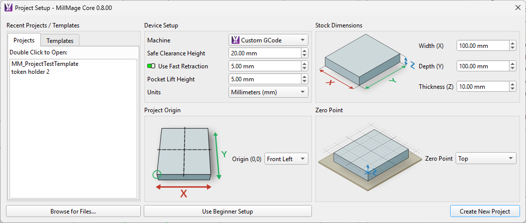
Setup your project in the Project Setup Window or Wizard. Make updates to stock dimensions, workholding details, and movement parameters at any time by selecting File → Project Setup Edit.
Import 3D Model
Import a 3D model by selecting File → Import. Use the Import 3D Model wizard to rotate and scale your 3D model before creating a depth map.
Video: Import 3D Model (0:00/10:45)
Create and Insert 3D Model Depth Map
Edit the depth map after importing your 3D model. Change the settings as needed to highlight the desired features, trim off unseen portions of the model by adjusting the depth cutoff, activating Generate Outline, and select Insert 3D Model.
Toggle On Generate Outline For Easy Design Isolation
Isolating a Depth Map
Toggle on Generate Outline to make removing material from around the relief carving with a Pocket operation easier.
Create and Insert 3D Model Depth Map
Follow the Create a Depth Map instructions to convert your 3D model into a 2D depth map and activate Generate Outline to create an outline of your design as an additional object. Export your depth map and outline by selecting Insert 3D Model and scale/position your depth map as desired on your workpiece.
Creating Depth Map Outlines After Depth Map Creation
Right-click on the depth map and select Generate Outline. A closed path outline will be created.
If the Generate Outline option is not present, use the built in Trace Image tool to create an outline that can be used with an externally bounding shape to carve out the material surrounding your design with a Pocket operation.
Limit Carving to Design Only
Assign both the depth map and the depth map outline to your 3D relief operation to limit the relief carving area.
Warning
Wider tools may impact and/or cut beyond the shapes assigned to the current operation. Always review the upcoming travel and cuttings moves in the Preview window.
Removing Additional Material
Clear out more material beyond the 3D relief carving by assigning the depth map outline and a surrounding shape to a Pocket operation.
Video: Create Depth Map (4:51/10:45)
Setup 3D Relief Roughing Operation
Setup a fast 3D relief roughing pass with larger diameter tooling to remove a bulk of the material.
Video: Setting up 3D Relief Roughing Operations (8:55/10:45)
Setup 3D Relief Finishing Operation
Run a slower, finer 3D relief finishing pass with a smaller-diameter tapered ball nose mill to carve free the final fine details after running a fast 3D relief roughing pass with larger diameter tooling to remove a bulk of the material.
Video: Setting up 3D Relief Finishing Operations (9:51/10:45)
Set Order of Operations
Adjust the operations listed in the Operations window to match this example workflow, making sure that the only operations with Output active match your installed tooling:
| Operations Order | Assigned Shapes to Operation | Recommended Tooling |
|---|---|---|
| 1. 3D Relief Roughing | Depth map (+ outline optionally to define the carve area) | Larger diameter ball end or tapered ball end mill |
| 2. 3D Relief Finishing | Depth map (+ outline optionally to define the carve area) | Smaller diameter ball end or tapered ball end mill |
| 3. Optionally: Clearing Pocket | Bounding shape and depth map outline to create more space around design | Larger diameter flat end mill |
| 4. Optionally: Cut Out Profile | Outside shape or project shape with retaining tabs if cutting free | Flat end mill |
Preview Relief Carving
Open the Preview window to review the upcoming travel and cutting moves and close the Preview window once you are ready to produce your object.
Activate Control Mode and Set Project Zeros
Power on your CNC machine and connect MillMage to your machine with a USB cable if Direct Control of your machine is supported.
Need to Export GCode to Run On Your Machine?
Use the Export Operations wizard to export groups of operations into separate GCode files or with all operations combined into one GCode file to run the job from the machine or through another GCode sender.
Jump ahead to Start the Job to continue.
Activate Control Mode
Control Mode Overview
Control Mode is a focused view for MillMage that displays the windows needed to properly execute your job and create your product.
While in Control Mode you can:
- Review the GCode file sent to your machine line by line before production begins
- Home each axis if your CNC machine is equipped with endstops
- Jog the tool around the cutting area manually through on-screen controls, your keyboard number pad, and to user-set saved positions
- Probe the workpiece to set the workpiece origin automatically, or use optional accessories like Tool Length Probes
- Manually set the workpiece origin
- Precisely set the desired spindle speed RPM on compatible machines
- Access user-set GCode macros to make sending common or often used GCode commands easy and fast
- Watch a close-to-live wireframe representation of the position and toolpath of the active operations
- View the current tool position coordinates
- Manually activate/deactivate coolant and vacuum accessories
- View a live feed of both the GCode sent to your machine and the controller's responses in the Console window
- Adjust the feed rate and spindle speed during an active job up to 10% higher or lower
- Start, pause, resume, and stop your machining job
Control Mode can be activated in two ways through the Job Control window.
- By pressing the Process button, when the Require Control Mode Before Start/Send toggle is active and/or
- By pressing the Control Mode button, when the Require Control Mode Before Start/Send toggle is off
Need to Make Changes? Return to Edit Mode.
Press the Edit Mode button in the Job Control window to exit Control Mode and return to a design-focused MillMage layout if any design or operation changes are needed. The Edit Mode button will not be enabled during an active job, and will only be enabled after the active job completes or is manually stopped.
Jog Tool and Set Project Zeros
-
Jog your tool close to the project workpiece using the controls in the Move window until the tool centerline is at your desired X and Y axis Project Origin point.
Be careful when jogging!
Before jogging your machine, check the following:
- Your jog speed is set to an appropriate value for your machine.
- The jog interval is set to a reasonable value.
- The tool has a clear travel path.
-
Lower the tool along the Z axis using smaller move increments until the tip of the tool is touching the material stock if using the top of the material as the Z axis zero point, or the wasteboard surface if using the bottom of the material as the zero point.
-
Use the XYZ 0 button to set the current tool position as the workpiece origin (0,0,0) for all three axes at once, or use the X0, Y0, and/or Z0 buttons to set your project zero on each axis when the tool is at each desired location.
Once zeroed, the Workpiece coordinates should display X: 0.00, Y: 0.00, and Z: 0.00.
Start the Job
Before you start the job,
- Put on your Personal Protection Equipment (PPE), including proper eye, ear, and body protection,
- Optionally activate your vacuum dust collection accessory, and
- Set your trim router (if equipped) speed and power the router on.
Press the Start button when connected to your CNC machine. Review and click through the Job Checklist if enabled, and your CNC machine will begin producing your design.
Always Monitor Your Machine
Never leave your CNC machine running unattended. CNC machines that run without supervision can cause fires, break tools, damage machines, and cause bodily harm.
Always watch your machine while your project is running.
Need to Export GCode to Run On Your Machine?
Use the Export Operations wizard to export groups of operations into separate GCode files or with all operations combined into one GCode file.
Once the initial roughing and finishing operations are complete, change tooling, zero your Z axis, and enable and run any remaining operations. After all the operations have ran, remove the workpiece from your CNC machine and use a cutting tool like an oscillating saw or rotary tool to free your relief carving from the material stock.
That's it! Show off your finished creation in the Finished Creations section of the MillMage User Forums at Forum.LightBurnSoftware.com.
Related Topics
- Import 3D Model | Create Depth Map
- Operation Settings Editor: 3D Relief Roughing
- Operation Settings Editor: 3D Relief Finishing
For more help using MillMage, please visit our forum to talk with MillMage staff and users, or email support.