Warning
This documentation is in active development. Content is being updated as feedback is reviewed. Your patience is appreciated.
Submit documentation feedback with the widget at the bottom-left of this window or by emailing [email protected].
Open a support ticket with the widget at the bottom-right or by emailing [email protected].
Edit Nodes
LightBurn Video
This video features our sister software, LightBurn. While there may be slight differences in appearance and layout, the demonstrated processes are similar in MillMage.
Quick Reference: Edit Nodes
-

Edit vector paths by moving, changing, or deleting nodes, lines, and curves.
-
Location
Tools → Edit Nodes
-
Keyboard Shortcuts
Windows: Ctrl+`
Mac: Cmd+`
Edit Nodes allows you to make precise, granular edits to vector paths, by controlling the placement and behavior of nodes (points in space, sometimes called anchor points) which are linked by straight lines or curves. The curved lines are described by the length and direction of handles (tangents) which appear on one or both nodes at either end of a curve.

Using Edit Nodes
To enable Edit Nodes, click on the Edit Nodes icon in the Creation Toolbar or press Ctrl/Cmd + ` on your keyboard.

If you already have a valid object (or objects) in your selection, its nodes will appear. If you do not have anything currently selected, click an object to view and edit its nodes.
What is a valid object?
The Edit Nodes tool works on vector paths. Paths must be ungrouped. Text Objects, Primary Shapes, and Barcodes must be converted to a path before using Edit Nodes.
Edit Nodes Toolbar
When you enable the Edit Nodes tool, an additional toolbar will appear to the right of the Creation Toolbar.
Hover over any button in the Edit Nodes Toolbar to see a tooltip explaining the action it will perform.
Click the enable a given type of action, then click on a valid node or line in your Workspace to perform that action.
LightBurn Video
This video features our sister software, LightBurn. While there may be slight differences in appearance and layout, the demonstrated processes are similar in MillMage.

Mouse Actions
With the Select action enabled in the Edit Nodes Toolbar, you can select and adjust nodes and lines directly with your mouse.
-
Click and and drag on nodes, handles, or curves to move them.
-
Click any node or handle to select it, and then use the keyboard arrow keys and modifier keys to move it by the increments set in the Shape Move Increments fields in the Settings window.
-
With a node or handle already selected, hold Shift while clicking on another node or handle to add it your selection, then drag or use the arrow keys to move each selected node or handle in unison.
-
Hold Ctrl/Cmd and click to toggle whether or not a node is selected.
-
Click any blank space to deselect all nodes.
-
Click any straight line and drag to automatically turn it into a curve.
-
Drag disconnected nodes on top of one another to automatically join them, turning the lines on either side into a single shared path.

Keyboard Actions

Each of the actions in the Edit Nodes Toolbar has a corresponding hotkey, listed below, that you can use to edit and manipulate lines, curves, and nodes.
You can quickly reference the keyboard commands for each of these at any time by hovering over the Edit Nodes tool in the toolbar.
| Action | Key | Description | Method |
|---|---|---|---|
| Delete node | D | Delete nodes and combine adjacent lines | Hover over a node (or select multiple nodes) and press key |
| Insert | I | Insert node anywhere on path | Hover over curve or line and press key |
| Insert node at midpoint | M | Insert node at the halfway point between two nodes | Hover over curve or line and press key |
| Convert smooth node to corner | C | Convert node to corner (curve handles will have independent angles) | Hover over smooth node and press key |
| Smooth corner node | S | Convert node to smooth (curve handles will have same angle) | Hover over corner node and press key |
| Break shape at point | B | Open path at node | Hover over a node and press key (move one of the nodes to reveal the gap) |
| Delete line | D | Delete line or curve (open or split path) | Hover over a line or curve and press key |
| Convert curve to line | L | Convert to line (straighten a curve and remove handles) | Hover over a curve and press key |
| Convert line to smooth curve | S | Convert to curve (add handles either side of line) | Hover over line and press key |
| Align Selected | A | Rotate selection by aligning segment to nearest horizontal, vertical, or 45° angle — all selected objects will rotate along with the segment | Hover over line and press key |
| Trim line | T | Cut line under mouse back to the next place it intersects with another line | Hover over curve or line and press key |
| Extend line | E | Extend line to nearest intersecting path | Hover over an open end point and press key |
Node Types
The shape, size, and color of a node all give you important information about the node.
Having trouble seeing the nodes?
If you're having trouble seeing your nodes, go to the Display tab of Settings/Preferences and increase the size of your nodes with the Cursors / Nodes slider.
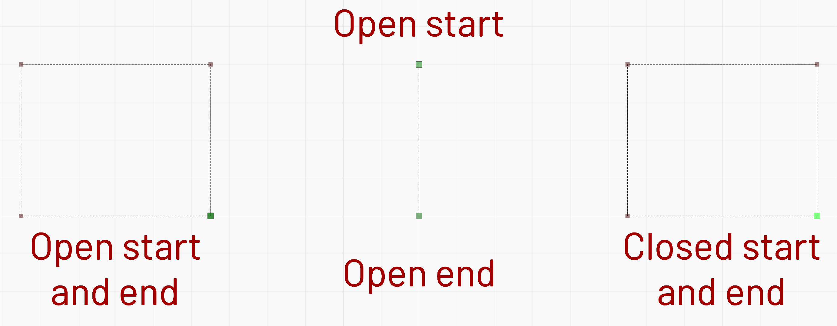 .
- Square nodes represent corner nodes.
- Round nodes represent smooth or bezier nodes, which have handles that can adjust the curves going in and out of them.
- Large nodes are start or end points of the shape.
- Large bright green nodes are closed nodes - they're the start node and end point of a closed shape. You can see an example in the shape all the way on the right in the screenshot above, labeled "Closed Start and End".
- Large dark green nodes with a black outline are the start node of an open shape. You can see an example in the line in the middle of the screenshot above, labeled "Open Start".
- Large dark green nodes with a light gray outline are the end node of an open shape. You can see an example in the line in the middle of the screenshot above, labeld "Open End".
- Large dark green nodes with a medium gray outline are the start node and end node of an open shape overlapping, which can result in a shape looking like it should be closed while actually being open. You can see an example in the shape all the way on t he left in the screenshot above, labeled "Open Start and End". Read more at Open Vs. Closed Shapes.
Snap to Existing Geometry
Snapping allows you to align your nodes or handles to specific points on existing objects.

Constrain Movement
Hold Shift while moving a node or handle to constrain movement to a 90° or 45° angle from its starting position, indicated by temporary guidelines in your Workspace.
If you select multiple nodes or handles at once, only the movement of the last-selected node or handle will be constrained, and the other nodes or handles will move along with it.

Requirements
-
You can only use Edit Nodes with paths. You can create paths with Draw Lines or the Trace Image tools. Otherwise you can Import vector objects into MillMage from another source.
-
To use Edit Nodes with other, built-in vector objects, you need to turn them into standard paths. This requirement applies to:
- Text Objects
- Primary Shapes: Rectangles, Ellipses, and Polygons
- Barcodes
Converting objects to paths
There are two ways to do convert your object to a standard path.
- With the Edit Nodes tool open, double-click on the shape to convert it to a path. If you're already in the Edit Nodes tool, hovering over a shape that needs to be converted will show a tool tip warning you "This is an object, like a rectangle or text. Double-click it to convert it to an editable path."
- Go to Edit → Convert to Path to turn them into standard paths.
-
You cannot use Edit Nodes with Grouped objects. Ungroup them first.
Trim and Extend Demo
LightBurn Video
This video features our sister software, LightBurn. While there may be slight differences in appearance and layout, the demonstrated processes are similar in MillMage.
There is also a separate tool, Trim Shapes that you can use to perform the Trim Line function.
LightBurn Video
This video features our sister software, LightBurn. While there may be slight differences in appearance and layout, the demonstrated processes are similar in MillMage.
Related Topics
- Draw Lines
- Trim Shapes
- Snapping
- Selection
- Images vs. Vectors
- Open vs. Closed Shapes
- Auto-Join Selected Shapes
- Break Apart
- Trace Image
For more help using MillMage, please visit our forum to talk with MillMage staff and users, or email support.